<Huawei>system-view Enter system view, return user view with Ctrl+Z. [Huawei]interface g0/0/0 [Huawei-GigabitEthernet0/0/0]ip address 192.168.1.254 24 Dec 12 2021 15:40:23-08:00 Huawei %%01IFNET/4/LINK_STATE(l)[0]:The line protocol IP on the interface GigabitEthernet0/0/0 has entered the UP state. [Huawei-GigabitEthernet0/0/0]int g0/0/1 [Huawei-GigabitEthernet0/0/1]ip address 1.1.1.1 24 Dec 12 2021 15:41:05-08:00 Huawei %%01IFNET/4/LINK_STATE(l)[1]:The line protocol IP on the interface GigabitEthernet0/0/1 has entered the UP state.
R2的配置:
1 2 3 4 5 6 7 8 9 10
<Huawei>system-view Enter system view, return user view with Ctrl+Z. [Huawei]interface g0/0/0 [Huawei-GigabitEthernet0/0/0]ip address 1.1.1.2 24 Dec 12 2021 15:46:22-08:00 Huawei %%01IFNET/4/LINK_STATE(l)[0]:The line protocol IP on the interface GigabitEthernet0/0/0 has entered the UP state. [Huawei-GigabitEthernet0/0/0]int g0/0/1 [Huawei-GigabitEthernet0/0/1]ip address 192.168.2.254 24 Dec 12 2021 15:46:45-08:00 Huawei %%01IFNET/4/LINK_STATE(l)[1]:The line protocol IP on the interface GigabitEthernet0/0/1 has entered the UP state.
2.配置静态路由
R1的配置:
1
[Huawei]ip route-static 192.168.2.0 24 1.1.1.2
R2的配置:
1
[Huawei]ip route-static 192.168.1.0 24 1.1.1.1
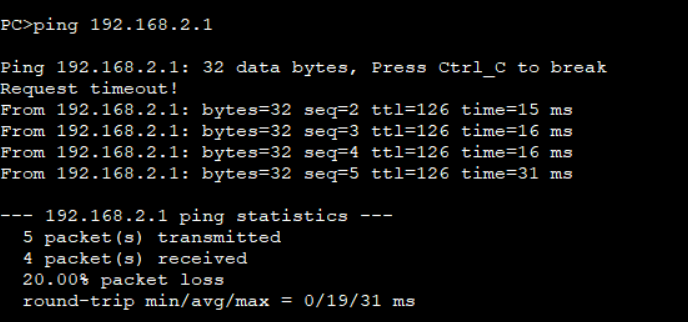
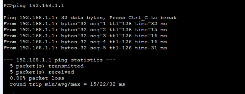
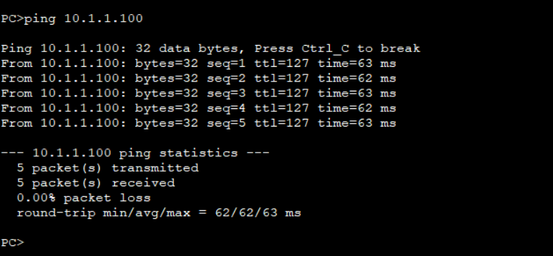
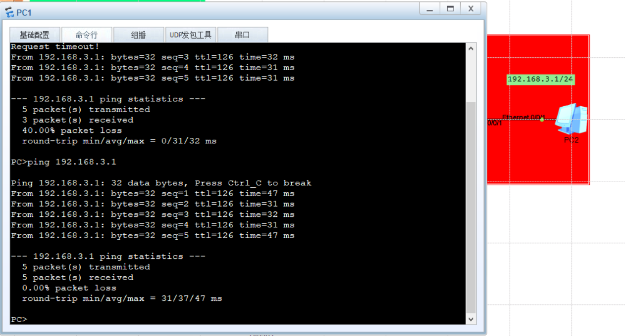
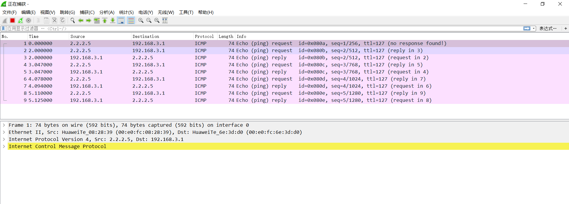
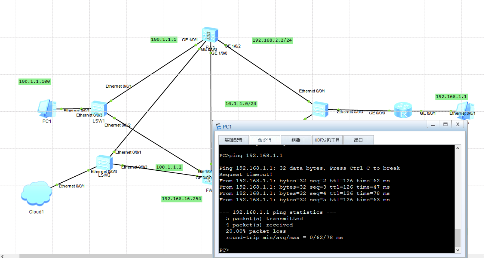
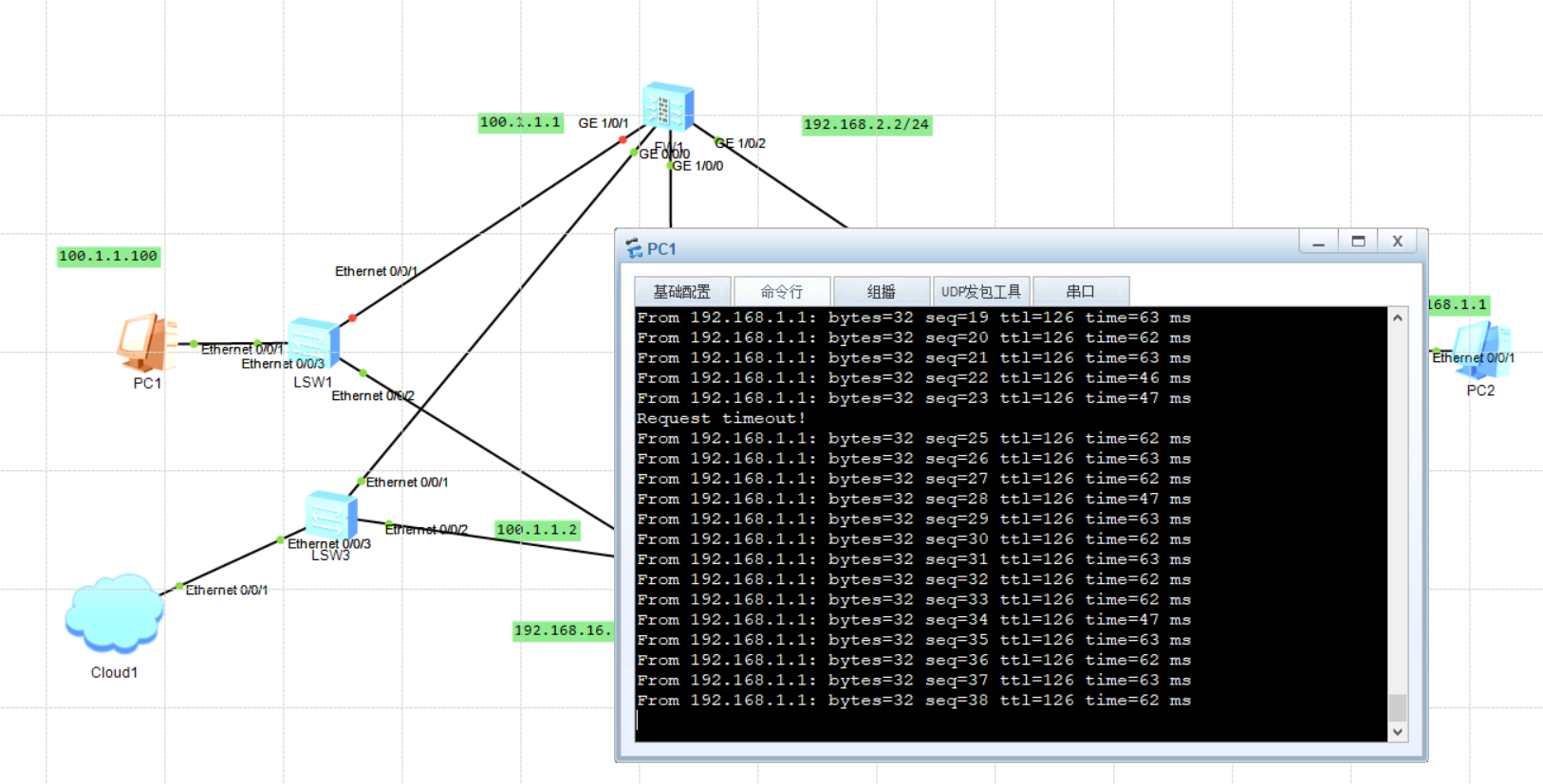
3.测试PC互通性
PC1:
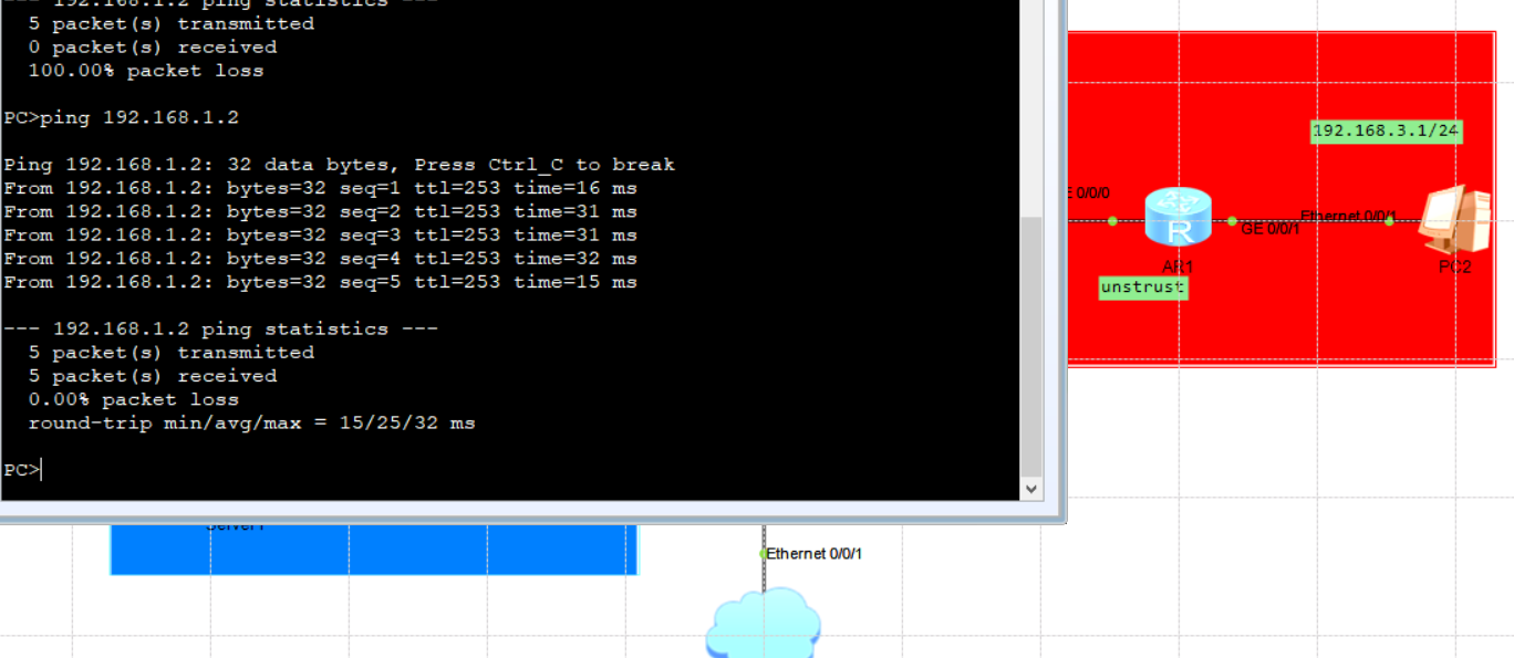
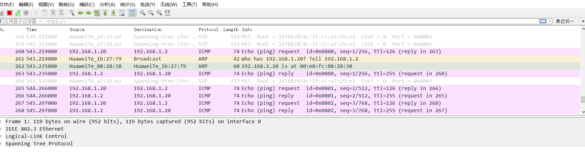
PC2:
至此,实验三完成
实验四(防火墙安全策略实验)
实验目的
理解安全策略原理
理解不同安全域之间的关系
掌握命令行和web方式配置安全策略
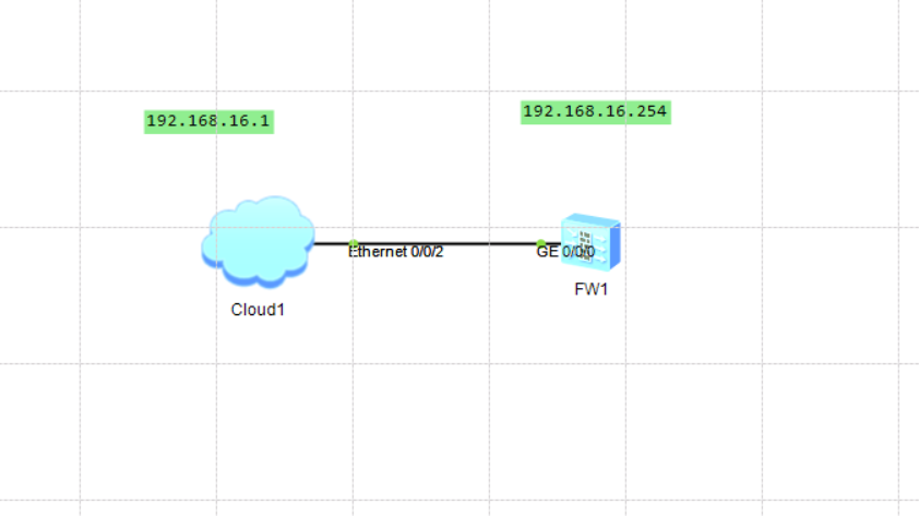
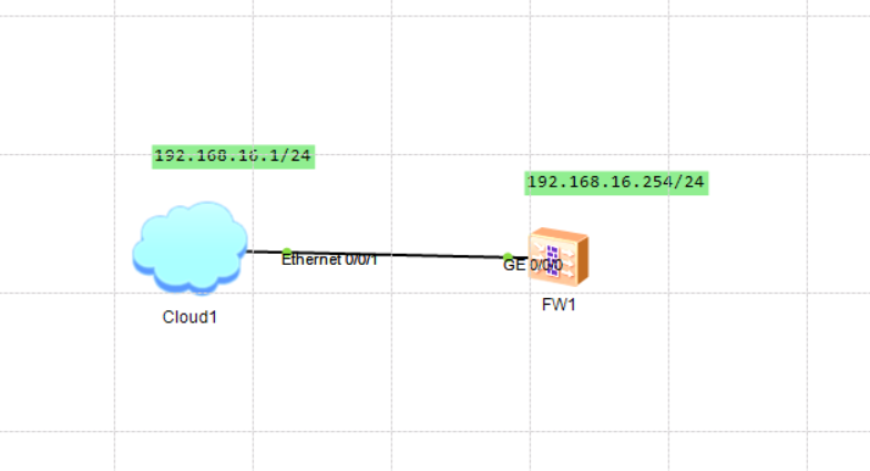
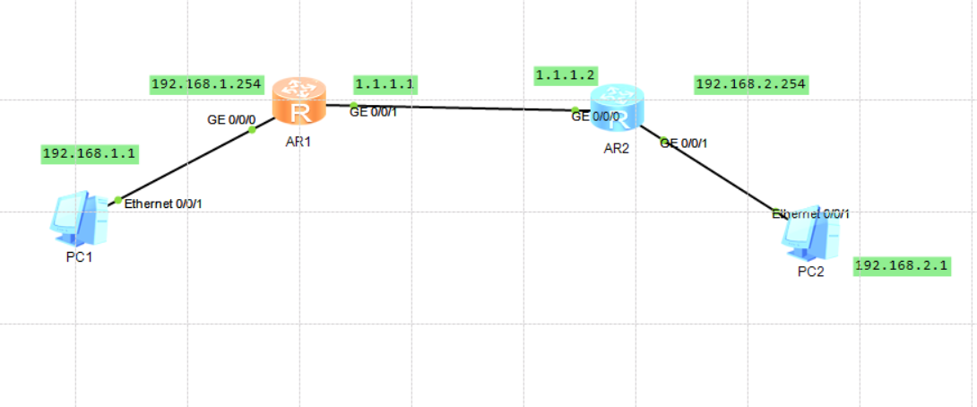
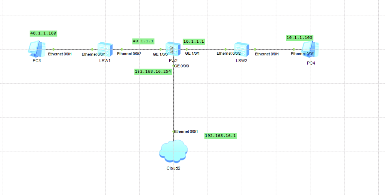
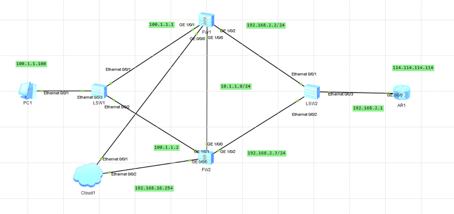
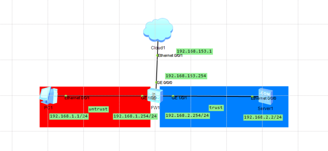
实验TOP图
配置思路
配置设备IP地址及其所属的安全域
配置域间安全策略
配置步骤
命令行配置:
IP地址配置
1 2 3 4 5 6 7 8 9 10 11 12 13 14 15 16 17
<USG6000V1>system-view Enter system view, return user view with Ctrl+Z. [USG6000V1]int g1/0/0 [USG6000V1-GigabitEthernet1/0/0]ip address 40.1.1.1 24 Dec 12 2021 08:23:07 USG6000V1 %%01IFNET/4/LINK_STATE(l)[0]:The line protocol IP on the interface GigabitEthernet1/0/0 has entered the UP state. Dec 12 2021 08:23:07 USG6000V1 %%01RM/4/ROUTERID_CHANGE(l)[1]:The router ID is 4 0.1.1.1. (InstanceID=0) [USG6000V1-GigabitEthernet1/0/0]int g1/0/1 [USG6000V1-GigabitEthernet1/0/1]ip address 10.1.1.1 24 Dec 12 2021 08:25:20 USG6000V1 %%01IFNET/4/LINK_STATE(l)[2]:The line protocol IP on the interface GigabitEthernet1/0/1 has entered the UP state. [USG6000V1-GigabitEthernet1/0/1]int g0/0/0 [USG6000V1-GigabitEthernet0/0/0]ip address 192.168.16.254 24 Dec 12 2021 08:26:05 USG6000V1 DS/4/DATASYNC_CFGCHANGE:OID 1.3.6.1.4.1.2011.5.25 .191.3.1 configurations have been changed. The current change number is 4, the c hange loop count is 0, and the maximum number of records is 4095.
配置trust与untrust区域的转发策略
1 2 3 4 5 6 7 8 9 10 11 12 13 14 15
[USG6000V1]security-policy [USG6000V1-policy-security]rule name trust_untrust Dec 12 2021 08:30:25 USG6000V1 DS/4/DATASYNC_CFGCHANGE:OID 1.3.6.1.4.1.2011.5.25 .191.3.1 configurations have been changed. The current change number is 5, the c hange loop count is 0, and the maximum number of records is 4095. [USG6000V1-policy-security-rule-trust_untrust]source-zone trust Dec 12 2021 08:30:35 USG6000V1 DS/4/DATASYNC_CFGCHANGE:OID 1.3.6.1.4.1.2011.5.25 .191.3.1 configurations have been changed. The current change number is 6, the c hange loop count is 0, and the maximum number of records is 4095. [USG6000V1-policy-security-rule-trust_untrust]destination-zone untrust [USG6000V1-policy-security-rule-trust_untrust]action permit Dec 12 2021 08:30:55 USG6000V1 DS/4/DATASYNC_CFGCHANGE:OID 1.3.6.1.4.1.2011.5.25 .191.3.1 configurations have been changed. The current change number is 8, the c hange loop count is 0, and the maximum number of records is 4095. [USG6000V1-policy-security-rule-trust_untrust]quit
绑定接口区域,并配置一条默认路由,这里是交换机不同加默认路由
1 2 3 4 5 6 7 8 9 10 11
[USG6000V1]firewall zone trust [USG6000V1-zone-trust]add interface GigabitEthernet 1/0/0 Dec 12 2021 08:33:55 USG6000V1 DS/4/DATASYNC_CFGCHANGE:OID 1.3.6.1.4.1.2011.5.25 .191.3.1 configurations have been changed. The current change number is 9, the c hange loop count is 0, and the maximum number of records is 4095. [USG6000V1-zone-trust]quit [USG6000V1]firewall zone untrust [USG6000V1-zone-untrust]add interface GigabitEthernet 1/0/1 Dec 12 2021 08:34:25 USG6000V1 DS/4/DATASYNC_CFGCHANGE:OID 1.3.6.1.4.1.2011.5.25 .191.3.1 configurations have been changed. The current change number is 10, the change loop count is 0, and the maximum number of records is 4095.
结果
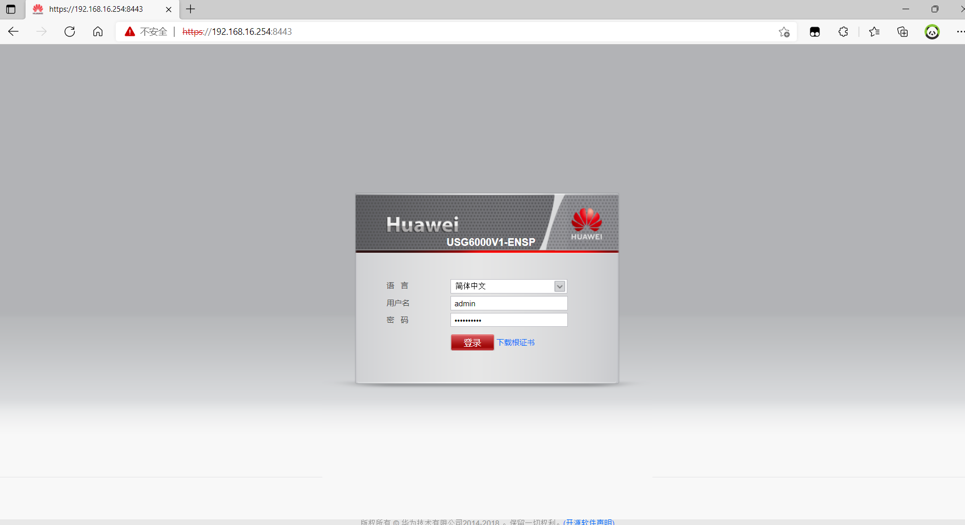
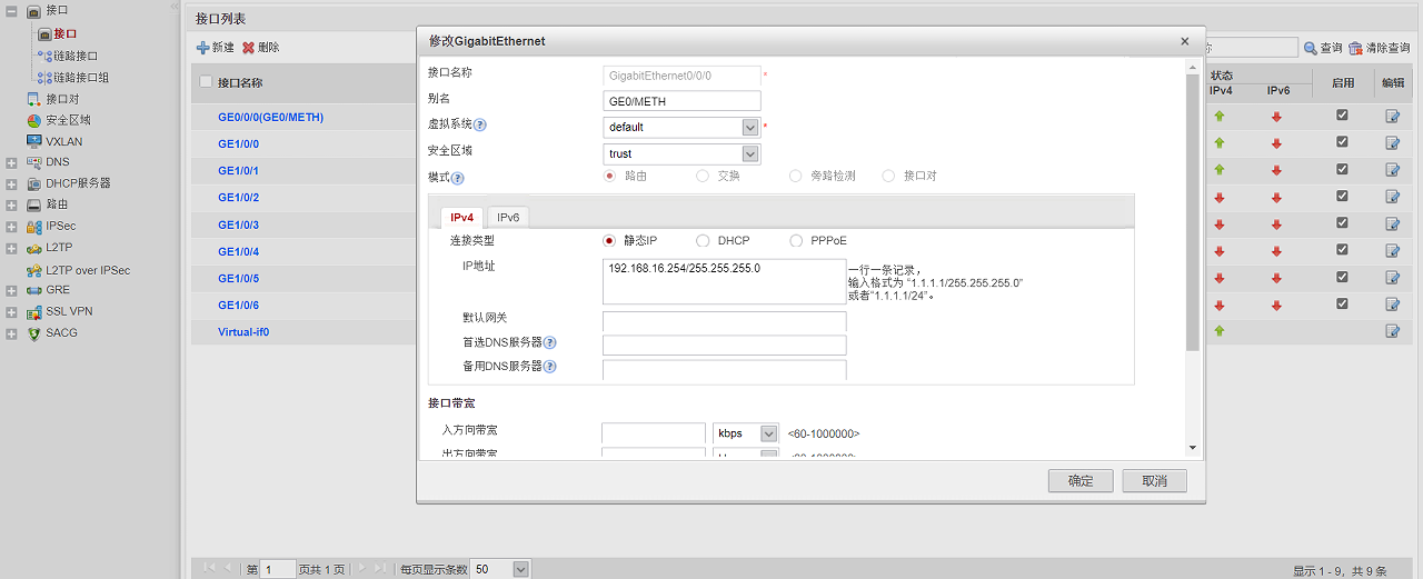
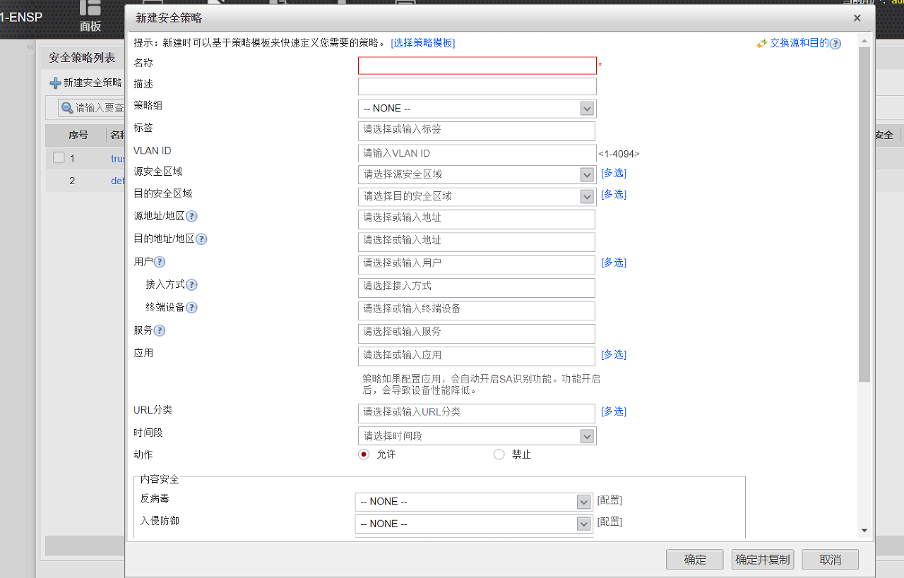
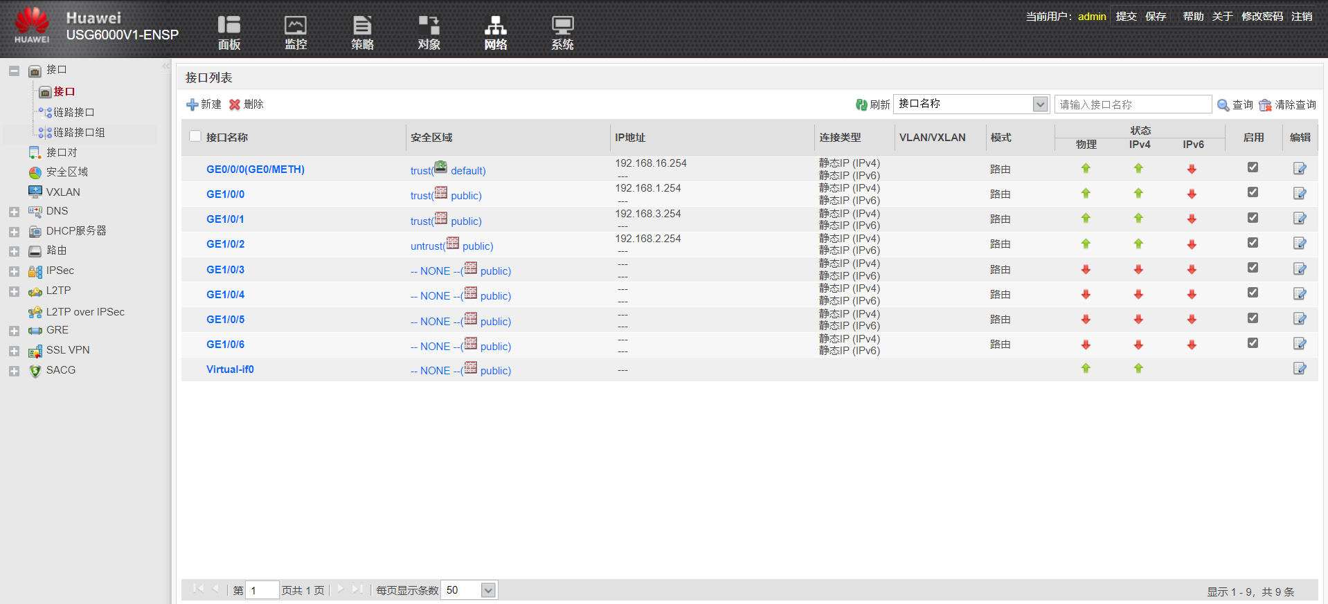
web配置:
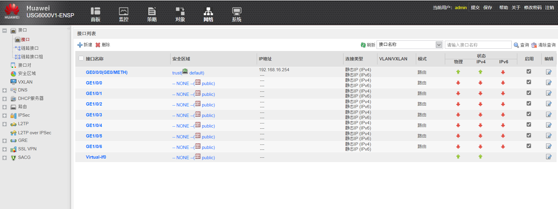
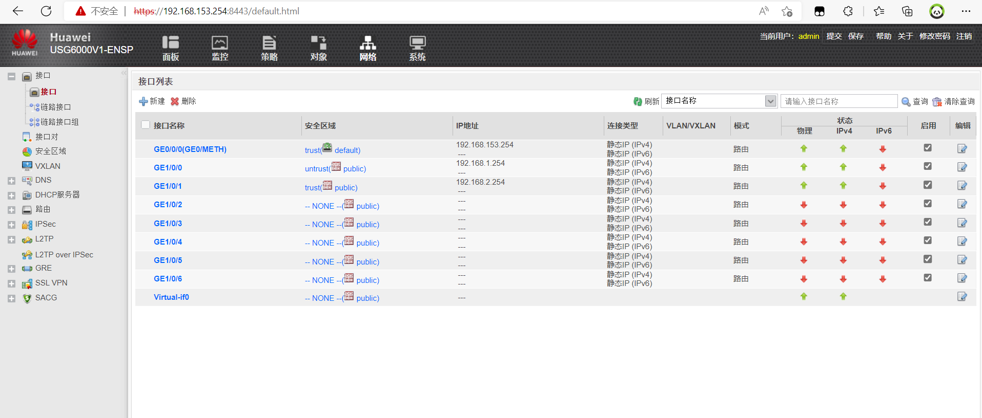
接口IP地址及安全区域配置,点击接口名称即可配置,这里不做过多演示,网络>>接口
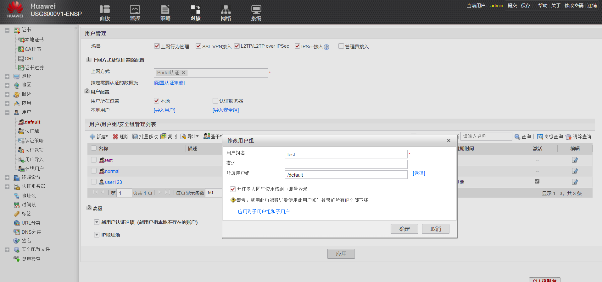
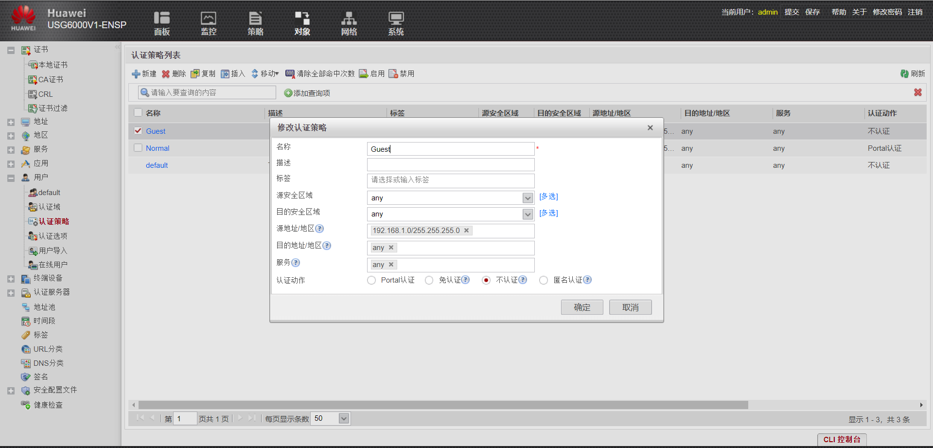
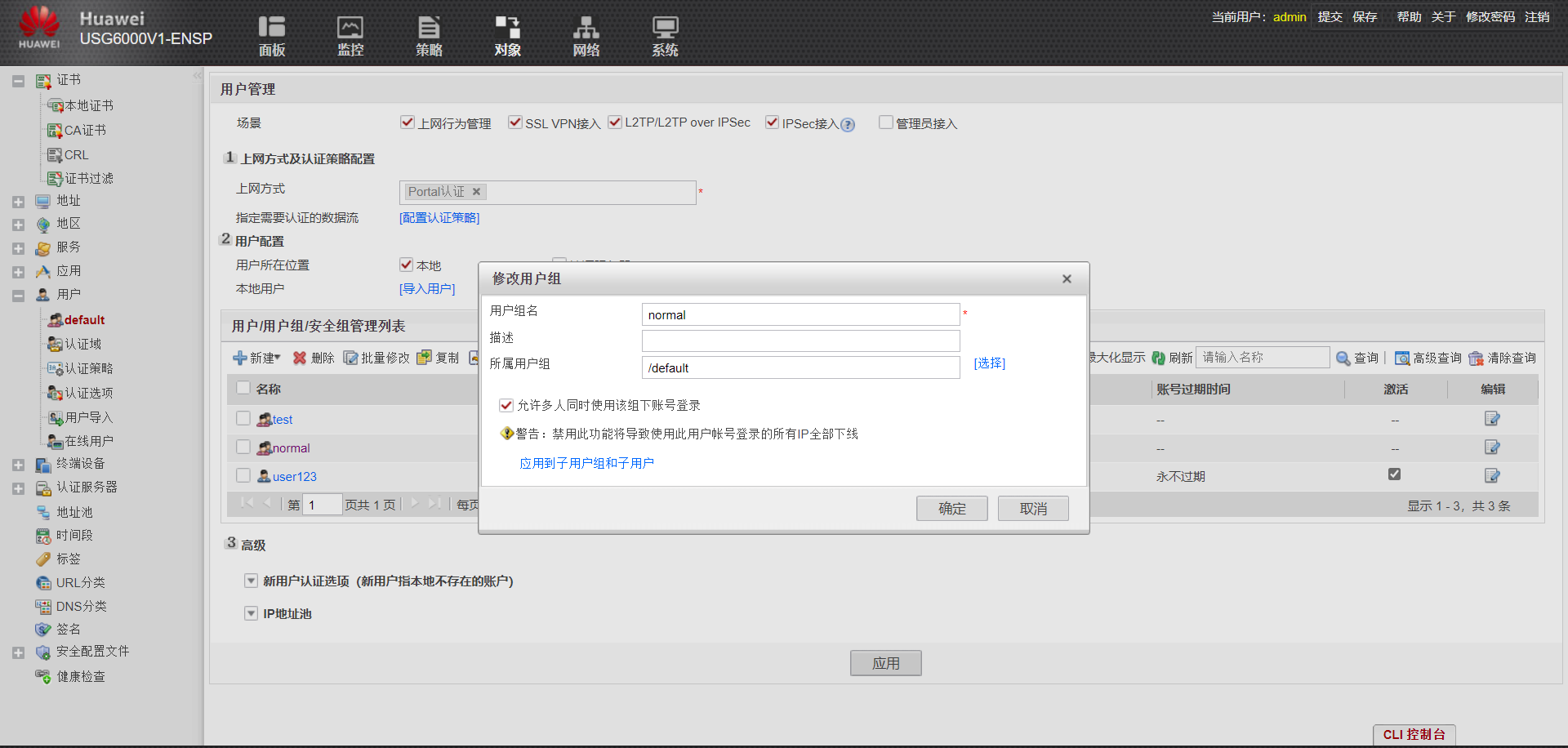
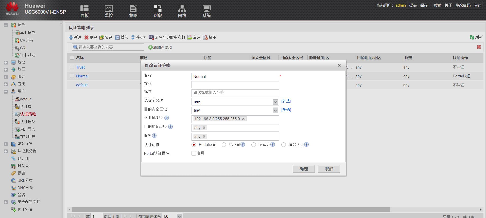
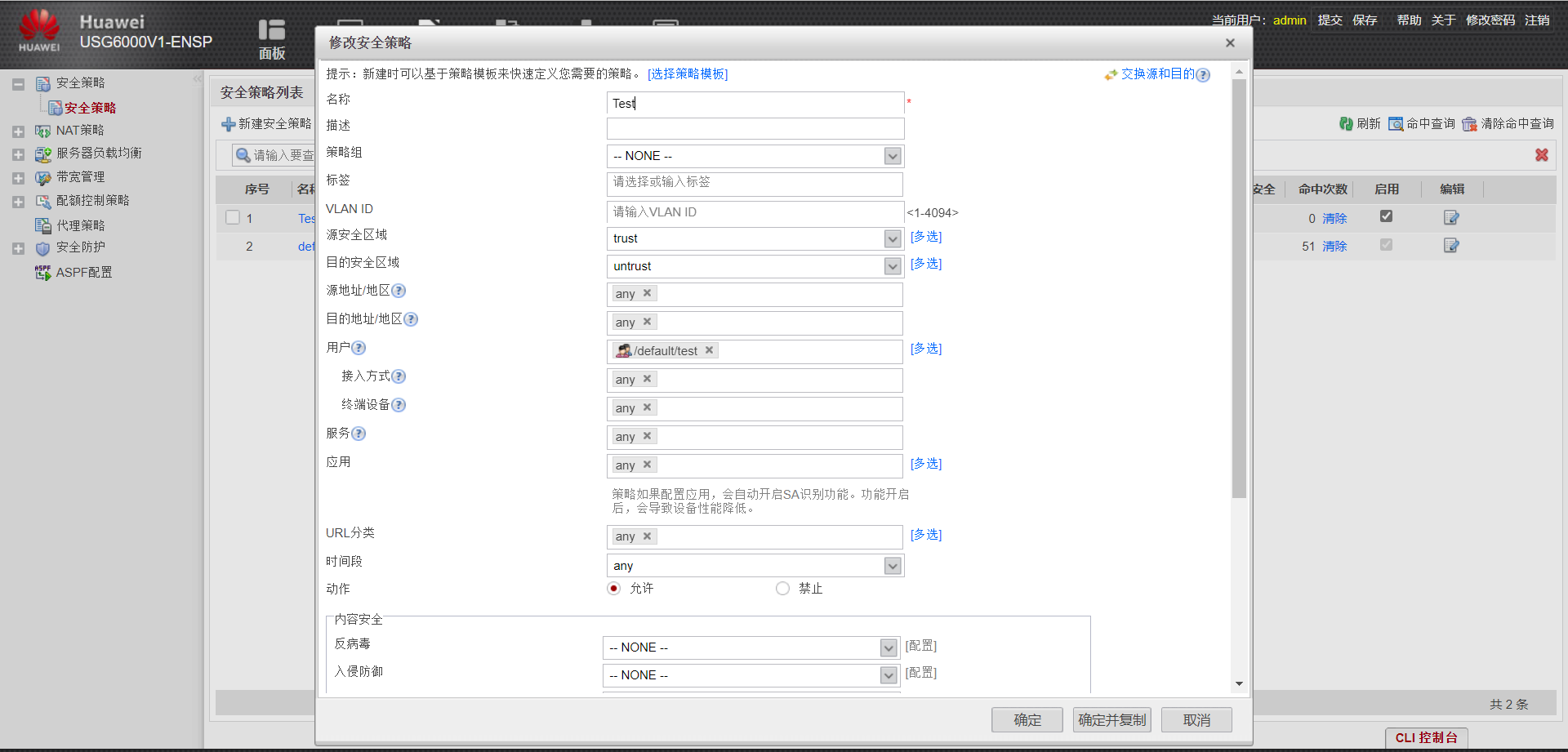
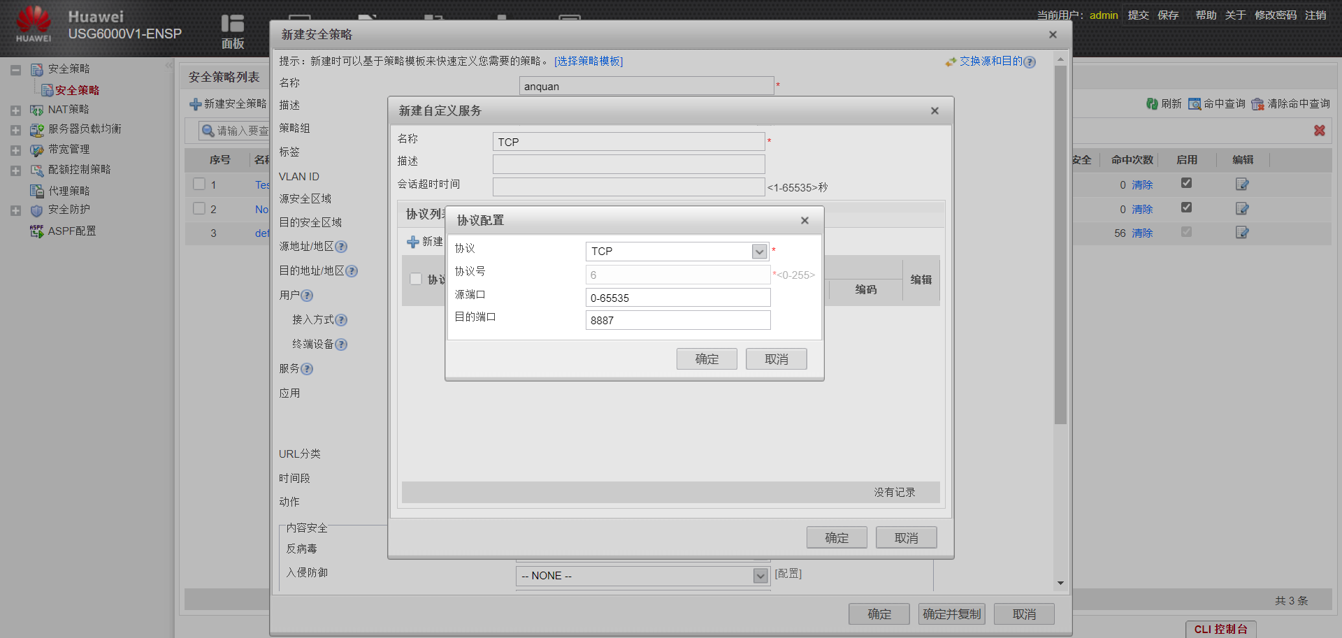
安全策略,策略>>安全策略>>新建安全策略;可以配置名字源目安全区域
至此,实验四完成
实验五(NAT server&源NAT实验)
实验目的
理解源NAT应用场景及原理
理解NAT server 应用场景及原理
掌握通过命令行和web方式配置防火墙NAT server&源NAT命令
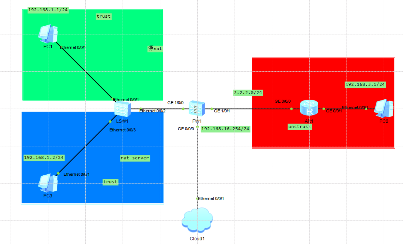
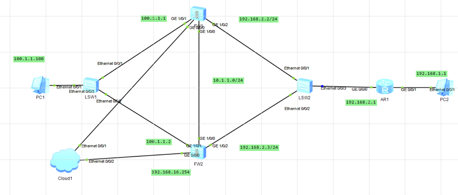
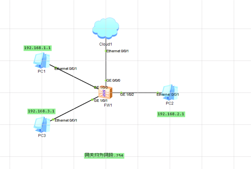
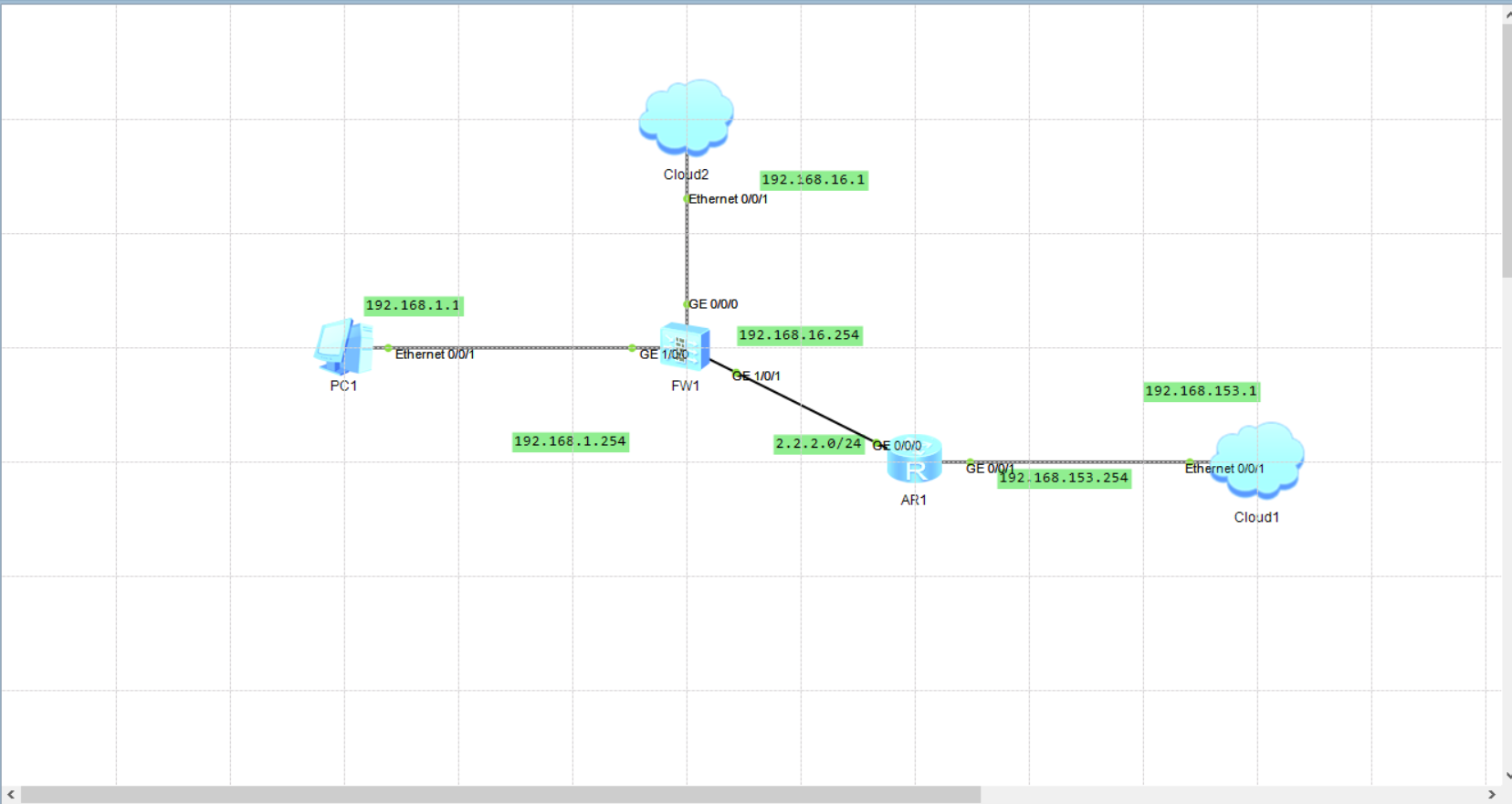
实验TOP图
配置思路(源NAT)
1.红区模拟外网,绿区蓝区为内网,通过源NAT转换实现内外网互通
2.配置基本的IP地址和所属安全域,并且放行对应的安全策略
3.创建NAT地址池
4.配置NAT策略
配置步骤-CLI
防火墙IP地址、默认路由配置
1 2 3 4 5 6 7 8 9 10
<USG6000V1>system-view [USG6000V1]int g1/0/0 [USG6000V1-GigabitEthernet1/0/0]ip ad 192.168.1.254 24 [USG6000V1-GigabitEthernet0/0/0]int g1/0/1 [USG6000V1-GigabitEthernet1/0/1]ip ad 2.2.2.1 24 [USG6000V1-GigabitEthernet1/0/1]int g0/0/0 [USG6000V1-GigabitEthernet0/0/0]ip ad 192.168.16.254 24 [USG6000V1-GigabitEthernet0/0/0]service-manage https permit [USG6000V1-GigabitEthernet0/0/0]q [USG6000V1]ip route-static 0.0.0.0 0 2.2.2.2
路由器IP地址、默认路由配置
1 2 3 4 5 6 7 8
<Huawei>system-view Enter system view, return user view with Ctrl+Z. [Huawei]int g0/0/1 [Huawei-GigabitEthernet0/0/1]ip ad 192.168.3.254 24 [Huawei-GigabitEthernet0/0/1]int g0/0/0 [Huawei-GigabitEthernet0/0/0]ip ad 2.2.2.2 24 [Huawei-GigabitEthernet0/0/0]q [Huawei]ip route-static 0.0.0.0 0 2.2.2.1
区域和安全策略(防火墙一定要给接口加区域,不然无法转发路由)
1 2 3 4 5 6 7 8 9 10 11 12 13
[USG6000V1]firewall zone trust
[USG6000V1-zone-trust]add interface GigabitEthernet 1/0/0
[USG6000V1-zone-trust]q
[USG6000V1]firewall zone untrust
[USG6000V1-zone-untrust]add interface GigabitEthernet 1/0/1
[USG6000V1-zone-untrust]q
[USG6000V1]security-policy
[USG6000V1-policy-security]rule name trust_untrust
[USG6000V1-policy-security-rule-trust_untrust]source-zone
[USG6000V1-policy-security-rule-trust_untrust]source-zone trust
[USG6000V1-policy-security-rule-trust_untrust]destination-zone untrust
[USG6000V1-policy-security-rule-trust_untrust]action permit
[USG6000V1-policy-security-rule-trust_untrust]quit
[USG6000V1]security-policy [USG6000V1-policy-security]rule name ser_nat [USG6000V1-policy-security-rule-ser_nat]source-zone untrust [USG6000V1-policy-security-rule-ser_nat]destination-zone trust [USG6000V1-policy-security-rule-ser_nat]action permit
配置NAT地址池
1
2
3
4
5
6
7
[USG6000V1]nat address-group serpool
[USG6000V1-address-group-serpool]s
[USG6000V1-address-group-serpool]section
Dec 15 2021 12:22:17 USG6000V1 DS/4/DATASYNC_CFGCHANGE:OID 1.3.6.1.4.1.2011.5.25
.191.3.1 configurations have been changed. The current change number is 22, the
change loop count is 0, and the maximum number of records is 4095.
[USG6000V1-address-group-serpool]section 192.168.1.20 192.168.1.25